
What would you find?
Setting the Stage
Requirements
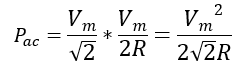
Performance Parameters
The Output Waveform
The Elements Ratings
Rectifier Structures
Half-wave
Circuit
Output Waveform
Elements Ratings
Full-wave: Centre-tap and Bridge type
Circuit
Output Waveform
Elements Ratings
Summary
Note: A better-edited version of this blog is available in original MS Word fromat, link below:
https://drive.google.com/file/d/1bhu2vm5EoFnPZkygcx5I9lvZ2xvTvkoS/view?usp=sharing
Setting the Stage……
Nearly a century ago two big stars of electrical engineering world were on a war. Thomas A. Edison had probably the toughest competitor anybody could have ever, it was Nikola Tesla. Morally it was a war of ideas and technically it a war of currents. Well established Thomas A. Edison was obsessed with his idea of direct current, young passionate Nikola Tesla however was confident of his visionary ideas of alternating current. Any of could have won the battle, but Nikola Tesla came out to be champion. Tesla’s brainchild the induction motor, and development of transformers won him the title to be one of greatest inventor of modern world, and thus paved way for AC technology to every corner of globe.
At that time Edison had a very narrow escape to win, if he had himself went on developing the HVDC technology for the transmission of bulk electrical power he would have won the battle, given the transistors was not invented till then!
So, it was an impossible task to efficiently step-up DC voltages to high level for efficient transmission, on the other hand the simplicity of induction motor had earned it a title of industrial horse and concretely popularized AC. From then on, the AC and DC technology have followed a graph with opposite slopes, AC being positive.
But the past few decades have shown a different trend, DC have begun to find its place in many applications in modern world of “electronics”.
DC currents have begun to show their capability to do a work more efficiently when backed by modern electronics. Single phase induction motors are now replaced by the efficient BLDCs, tube-lights has been replaced by LEDs, and what not.
Today’s hybrid power system with majority generation, transmission and distribution been AC and consumption shifting to DC, requires a very efficient AC-DC conversion, at all points, else we would be wasting our precious electrical energy in form of thermal waste uselessly heating our environment.
The most massive DC system in our present modern world is HVDC stations, the featured image!!
Take a look around, our laptop, mobile phones, TV sets, LEDs, numerous home gadgets run on DC.
So, we need a constant DC output from a 50/60 Hz sinusoidal AC waveform.
REQUIREMENTS
A dc voltage is defined as a voltage whose polarity remains the same, more accurately polarity doesn’t change. Terminal “A” at any point of time is at higher potential than terminal “B”. So, all the waveform which never crosses the x- axis qualifies to be called DC Voltage by this definition.
#stick some DC wave graphs
So, are they all the same, do they have same DC power delivering capability? Does any DC device like a battery, a DC motor, a LED, etc. will have same performance characteristics when operated by these DC voltages?
Clearly, we need to define which parameters differentiate one DC waveform from another.
To understand this, we need to zoom in, we need to see something which is not so apparent from the current point of view.
The Fourier transform of all these waves could give the real insights. As we all know Fourier transform is powerful mathematical technique to breakdown any signal/waveform into its component fundamental signals. It reveals the greatest mathematical truth and beautifully summaries that all the signal can be expressed as summation of a constant and sine and cosine components.
Once we get the spectrum of components of a waveform, we can now very easily comment about the capability of a DC waveform to do the work.
HOW?
Consider the electrolysis experiment, in which we pass a dc current to deposit some desired product on a given electrode.
When we excite the circuit with these different DC waveforms, Fourier series backs us to say that we are actually giving a sum of all the components calculated by this tool.
Result follows from this experiment is that the amount of deposition by a DC waveform only corresponds to the constant component of waveform (current/voltage). It is also quite obvious to say that all sine or cosine waveform component will not contribute to net deposition in their one time-period (due to reversing nature).
For any DC device powered by a DC current/voltage waveform, only the constant component is utilized for doing the useful work. For the sinusoid components the charge, deposition, torque, etc. is always zero in DC devices.
Before we jump in to see the parameter, let’s have a look on: what is RMS value of a waveform?
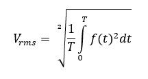
The book definition is, the RMS value is constant DC voltage equivalent of an AC voltage (or pulsating DC voltage) which will produce same resistive heating effect for a given resistor. So, power developed by an AC voltage is calculated and equated to that of equivalent constant DC voltage, hence we get RMS value.
We will use this definition throughout.
PERFORMANCE PARAMETERS
Consider this general rectifier layout diagram:

While analyzing the performance of any rectifier structure we have to consider two things, one is the characteristics of output for efficient conversion and second is the ratings of the elements used for the safety and economy purposes.
Let us see how and which parameters are used to analyze the output waveform?
The output waveform:
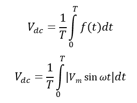
First using the Fourier series, we calculate the DC value of the output waveform.

Considering the time-period of waveform to be T.
Where,
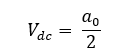
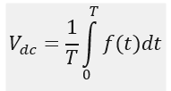
DC component is calculated as, which is also called average DC voltage:
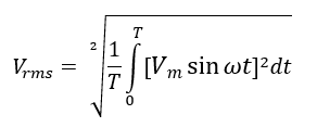
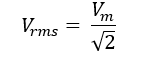
Now calculate the RMS value of this waveform, which is according to the definition;
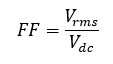
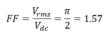
We define a term called Form factor as:
Now, the efficiency of rectification by common sense is ratio of actual DC power developed to the maximum power that could have been developed if the voltage has been pure DC, (assuming load to be purely resistive):
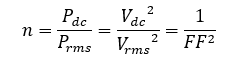
So, Form factor more or less gives the quantitative measure of rectification. The higher the DC content, lower the FF thus higher is the efficiency of rectification.
So, a good rectifier system must have low Form Factor, ideally 1!
But there exists a qualitative difference between two rectified waveforms having same form factor.
For example, consider a DC waveform from a rectifier as square wave and triangle wave.
The square wave of amplitude 1 and time-period T, then it can be calculated that Vdc= 0.5 V and Vrms= 0.707 V, Form factor is 1.414.

Now consider another DC waveform, a triangular wave of peak amplitude 1 and t1 = T/1.499, in this case Vdc =0.333 V and Vrms = 0.471 V, and thus form factor is 1.414.
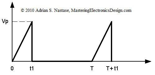
Though they have same FF but we can see they vary greatly in terms of smoothness, and that is particularly due to different AC components, defined as ripples.
Intuition can lead us to say that the ripple voltage must be the effective AC component of voltage, so the RMS of ripple voltage:
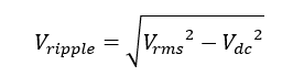
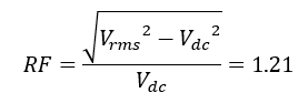
Ripple factor is defined to give the degree of smoothness of a rectified waveform, it is defined as ratio of RMS of ripple voltage to the RMS of DC voltage.
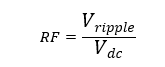
So not just high DC content is desired but also a desired degree of smoothness is expected. The second case becomes a necessity in field where precision is utmost like in particle accelerators, etc.
So, the RF is lesser for a smooth rectified waveform, ideally zero.
The elements ratings:
All the circuits elements which we will see later (transformers, diodes, capacitors, etc.) in rectifier circuits should be operated within their permissible ratings.
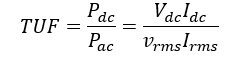
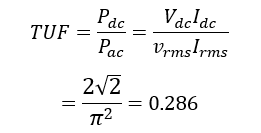
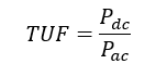
Almost every rectifier circuit is aided by a transformer to obtain the required voltage transformation. The rating of transformer to handle the power and current is also a critical performance parameter. We have defined Transformer Utilization Factor (TUF) to account the same.
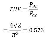
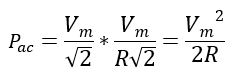
TUF is the ratio of DC power supplied to load to the total AC power at the secondary of transformer.
So,
![]()
and
![]()
Where Vrms and Irms are the rms value of voltage and current waveform at the secondary of the transformer.
There are certain operational limits of the diode which must be taken care under operation.
The Voltage stress occurring across the diode under non-conducting period must be less than the maximum voltage to cause rupture or breakdown of the diode, also called Peak Inverse Voltage (PIV) rating.
The current through diode must never exceed the peak forward current/average forward current defined limit, to check that the thermal limit of diode is not exceeded.
Elements ratings would be understood more clearly later.
RECTIFIER STRUCTURES
To understand the basics of different rectifier circuits we will first analyze them considering the ideal case- transformer is lossless, diode has no resistance, and load being purely resistive.
Half wave rectifier: This basic circuit is only used for low power rating applications. A diode of suitable ratings is used in series with load, diode conducts only in forward biased mode i.e. only when the voltage polarity across it is maintained, say positive. In next half-cycle the diode is reversed biased and the load current is zero.

THE OUTPUT WAVEFORM:
Voltage across load is:

Waveform:

Fourier series:
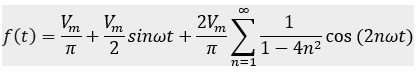
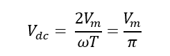
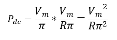
The DC component in waveform or the average DC voltage is:

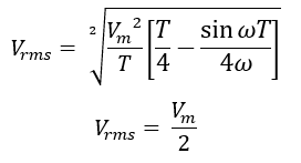
The RMS value of the output voltage is:

Using the trigonometric formula to get suitable form for integration:

Which on integrating and putting the limits simplifies to:
Now the form factor can be calculated as:
The ripple factor to get the qualitative index of the rectified output:
The efficiency of the rectification is:

THE ELEMENTS RATINGS:
Transformer Utilization factor:
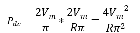
We have calculated Pdc as:
The voltage waveform at secondary is a sinusoidal transformed waveform of max amplitude as Vm.
The rms value of current in secondary is same as the load current.
We have:
PIV (Peak Inverse Voltage): In negative cycle the diode sees a Vm drop across it.
PFC (Peak Forward Current): It is the maximum instantaneous current through the diode in forward bias condition, considering resistive load R, we have:


CONCLUSION:
Half wave rectifier gives has following performance parameters:
- FF as 1.57 and efficiency of rectification as 40.5%, which means in the output waveform only 40.5% power is DC rest is AC component.
- RF as 1.21, which indicates not very smooth waveform.
- TUF is 0.286, which means the transformer must be (1/0.286 = 3.49) times higher rating that the actual power delivered to the load, so bigger transformer is required.
- PIV and PFC are calculated as above for selecting the diode.
Full-wave rectifier- Using center tapped transformer:

Voltage across load is:
![]()
Waveform:

Fourier series:

The waveform can be considered to be periodic in T/2 or in T, the calculation of parameter won’t be affected.
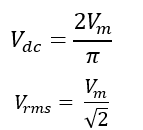
The average DC voltage is:

The RMS value of the output voltage is:
We can also directly find the RMS value, as it would be same as that of a sine wave, as no part of waveform is lost.
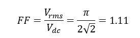
So, here the form factor is:
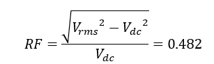
The ripple factor of the rectified output:
The efficiency of the rectification is:

THE ELEMENTS RATINGS:
Transformer Utilization factor:
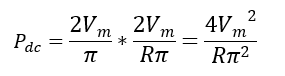
We have calculated Pdc as:
The total power is shared equally by two secondary windings of the center-tap transformer.
In each half winding, the voltage waveform at secondary is a sinusoidal transformed waveform of max amplitude as , so rms value of voltage in one winding is:
The rms value of current in secondary for one winding is same as that of the half-wave transformer (same current waveform): –
So, power rating of secondary is twice that of each winding:

We have:
PIV (Peak Inverse Voltage): In negative cycle the diode sees a Vm drop across it.
PFC (Peak Forward Current): It is the maximum instantaneous current through the diode in forward bias condition, considering resistive load R, we have:

Conclusion
Full-wave rectifier with center-tap transformer gives has following performance parameters:
- FF as 1.11 and efficiency of rectification as 81.16%, which means that the output waveform has 81.16 % of total power as DC rest as AC component.
- RF as 0.482, which indicates more smoother waveform.
- TUF is 0.573, which means the transformer must be (1/0.573 = 1.745) times higher rating that the actual power delivered to the load, so less big transformer is required.
- PIV and PFC for selecting the diode is same as that of half-wave rectifier.
Full-wave rectifier- Bridge type

Waveform:
Fourier series:
Only the elements rating would be affected, the waveform characteristics remains same as that of the previous case of center-tap transformer.
Clearly the form factor and the ripple factor will also remain the same:
![]()
The efficiency of the rectification is:

THE ELEMENTS RATINGS:
Transformer Utilization factor:
We have calculated Pdc as:
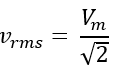
The rms voltage developing at the secondary winding is:
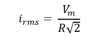
The rms value of current in secondary winding is same as the rms current through the load-
So, power rating of secondary of transformer is:
We have:
PIV (Peak Inverse Voltage): In negative cycle the Vm drop is shared equally by two identical diodes in series thus PIV rating of each diode is Vm/2.
PFC (Peak Forward Current): It is the maximum instantaneous current through the diode in forward bias condition, considering resistive load R, we have:


Conclusion
Full-wave rectifier with bridge-type gives has the following performance parameters:
- FF as 1.11 and efficiency of rectification as 81.16%, which means that the output waveform has 81.16 % of total power as DC rest as AC component.
- RF as 0.482, which indicates a more smoother waveform.
- TUF is 0.810, which means the transformer must be (1/0.810 = 1.234) times higher rating that the actual power delivered to the load, so less big transformer than the previous type is required.
- PIV of the diode is halved.
- PFC and average current remain same as that of half-wave.
- The current in transformer winding reverses unlike in centre-tap or half-wave rectifier structures where the current direction is remaining same and the possibility of core saturation is there.
SUMMARY

In the next blogs to come the following topics will be explored :
Real world approach for the circuits
Applications
Harmonics distortion on AC side
Study of different loads
Keep reading, keep learning!
AANTARAK DIVISION
TEAM CEV!!

 The MCU runs on 5V, means it will perform its functions within a range of 0-5V. So you need a 5V voltage regulator circuit which can be easily made using two capacitors (1uF and 10uF) and an IC LM7805. Now since our motors run on 12V, we will require a motor driver which converts these 5V signals to 12V i.e. L293D. The circuit connections for both are shown